9.3 DESIGN OF FLANGE JOINTS
The interconnecting lines of a rocket engine system must retain fluids at various pressures and temperatures. Each of these lines may have one or more mechanical joints requiring static seals to prevent leakage. The joint as an assembly must be capable of maintaining intimate conformance of seal and sealing surfaces throughout its operating life, regardless of all strains, loads, and thermal gradients. For line sizes of inch or larger, bolted flange joints are generally used in rocket engine design. The design of these flange joints is also applicable to other components, such as thrust chamber injector dome flanges and turbopump and valve housing flanges.
Flange Joint Design Considerations
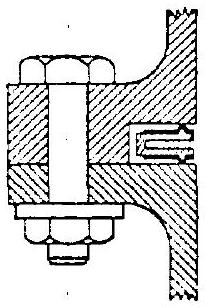
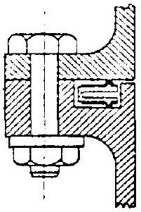
Figure 9-10 illustrates typical flange joints used in a propellant duct assembly. Most flange joints consist of three elements: the flanges, the fasteners (bolts and nuts), and the gasket. In addition to an effective gasket, a leaktight flange joint must have proper flanges and bolting. In flange joint structural design, the goal of optimum weight within safe stresses must consider the elastic behavior of the part.
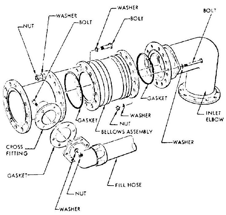 Figure 9-10.-Typical flange joints of a propellant duct assembly.
In addition to structural needs, other design considerations for flange joints are:
- Working temperature and pressure of the fluid. -These greatly affect the type of seal design and material. The problems of maintaining a leaktight flange joint are greatly compounded by temperature effects. Temperature differentials at the flange joints of rocket engines are apt to be large, because of steep heating and flow transients. They introduce thermal stresses and strains which may disturb the sealing. When designing an elevated temperature (or subzero) flange joint, the temperatures of the various parts should be analyzed to assess their effect on the sealing load. Ideally, thermal effects should neither loosen nor tighten the joint. In actual design the flange joint must be sufficiently elastic, so that sealing loads are at least maintained within reasonable limits.
- Degree of sealing.-For most applications it is sufficient to prevent mass flow as evidenced by liquid or gas tightness under soap bubble or immersion tests. When sealing the lighter gases ( and He ), diffusive flow through openings of molecular size may become significant.
- Gaskets.-The function of a gasket is to seal effectively between two flange surfaces. It is usually made of a material which will readily conform to the surfaces, or which is coated with a material so that when properly loaded, a barrier will be formed in depressed surface regions, preventing leakage of the contained fluid. Gaskets which damage the flange sealing surfaces are usually unsatisfactory, if the joint has to be repeatedly disassembled and reassembled. For these applications, gasket surfaces should always be softer than those of the flanges.
- Sealing surface condition.-As a rule, leakage will occur when the internal fluid pressure begins to exceed the compressive stress which holds the gasket in contact with the sealing surface. Radial scratches on the flange sealing surface tend to induce a lower gasket local compressive stress along that radial path, resulting in leakage. Conversely, if the flange sealing surface consists of concentric serrations, higher local compressive stress will be induced circumferentially along the serrations, and will seal higher internal pressures for a given nominal compressive stress of the gasket. The required sealing-surface finish is a function of gasket design. Generally, it ranges from a microinch finish of 32 to 125 rms , with concentric tool markings.
- Gasket loading. -The minimum requirement for good sealing of a flange joint is sufficient gasket precompression to close up all paths through which fluid flow could occur. Furthermore, the sealing load must be maintained so that a specific level of gasket compressive stress is induced to resist the internal fluid pressure.
- Seal drain.-In some applications, positive sealing at the flange joint is required. Dual (series) seals and overboard drain line are then provided (fig. 9-15).
Flange Joint Structural Design
Figure 9-11 presents the structural design configuration of a typical flange joint as frequently used in rocket engines. The flange ring, under various working loads, is subject to bending as shown exaggeratedly by the dotted lines. The bending moments may become quite large; the resulting stresses reach their maximum at corner , where the flange joins the wall of the duct.
The basic approach to the design of a flange joint is to prestress the flange bolts in tension
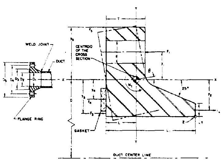 Figure 9-11. -Structural design configuration of a typical flange joint.
so that a gasket compressive stress is maintained to seal effectively against fluid leakage, under maximum working pressure and other loads. Defining a flange ring segment of unit length (i.e., 1 inch along the arc of a circle passing through the flange cross-section centroid) as a free body, the correlations between all forces acting on that segment, and the minimum required design llange bolt loading, are established as follows:
where (referring to fig. 9-11) diameter of the circle passing through the centroid of the flange ring cross section, in inside diameter of the flange and duct, in inside diameter of the gasket. in outside diameter of the gasket, in =internal fluid pressure, psi (the maximum working pressure should be used) force per unit length of the flange ring from bolt loading, lb/in force per unit length of the flange ring from longitudinal tension of the duct, force per unit length of the flange ring from internal pressure force per unit length of the flange ring from gasket loading, force per unit length of the flange ring from compression load at the flange outside diameter, lb/in required average gasket compressive stress, for proper seating against an internal fluid pressure , psi =gasket factor, a function of gasket design and to be determined experimentally; design values range from 0.8 to 10 flange factor, a function of flange configuration and its rigidity; design values range from 0.1 to 0.8 end loads on the duct due to inertia and thermal effects (tension or compression), lb minimum required design flange bolt loading, lb
Sample Calculation (9-1)
The following design data are given for the flange joint of the oxidizer-pump-discharge flexible duct of the A-1 stage engine:
Working pressure under normal steady operating conditions, 1505 psia Maximum fluid working pressure under occasional transient conditions, 1750 psia Inside diameter of the duct, Inside diameter of the gasket, Outside diameter of the gasket, End loads on the duct, due to thermal contraction, Gasket factor, Flange factor, Determine the minimum required design bolt loading of the flange joint.
Solution
We will use a maximum working pressure p = 1750 psia
From equation (9-5), the required average gasket compressive stress:
Combine equations (9-1) and (9-6):
Combine this and equations (9-2), (9-3), (9-4), and (9-7) to obtain the minimum required design bolt leading of the flange joint:
After the required design bolt loading has been determined, the number, size, and torque value of the bolts needed to produce that load must be chosen. Since tensile elasticity is advantageous, the use of small-diameter, highstrength bolts is desirable. Bolt spacing should be sufficiently close to insure a reasonably even distribution of the load around the gasket circumference. The following empirical correlation is recommended for maximum spacing to produce a tight joint:
where maximum bolt spacing, in d = nominal bolt dia, in flange thickness, in The general proportion of the flange ring may be determined by the following empirical equation (fig. 9-11):
where thickness of the duct wall, in, as determined by a hoop stress calculation overall axial length of the flange ring, in design factor, ranging from 4 to 6 design factor, ranging from 10 to 14 A taper angle of is generally used for the hub portion of the flange ring.
The stress and strain analysis of the flange ring may be treated as the twisting of a thick circular ring of uniform cross section under the influence of turning couples which are uniformly distributed along a circle passing through the centroid of the ring cross section. The following correlations approximate the maximum working stress and strain of a flange ring (refer to fig. 9-11):
where
| the moment of inertia of the ring cross section about the axis, in | |
|---|---|
| E | =modulus of elasticity of the flange material, psi |
| = angular displacement of the flange ring under maximum working pressure and loads, rad | |
| = flange ring maximum tensile stress, which occurs at the corner and is normal to the plane of figure 9-11, i.e., in the hoop direction |
Sample CaIculation (9-2)
With the data given in sample calculation (9-1), design the flange for the oxidizer pump discharge flexible duct of the A-1 stage engine, with the following recommended material and bolt data:
Flange and duct material, Inco 718 Minimum yield strength, Minimum ultimate strength, Modulus of elasticity, Duct weld efficiency, Bolt size and material, 5/16-24 A-286 (200000 psi ), stainless-steel bolt, 0.526 head dia Allowable ultimate bolt load, 10262 lb
Solution
Use the flange design and nomenclature shown in figure 9-11. From equation (2-8):
Design limit pressure
or Design limit pressure maximum transient pressure From equation (2-9), yield pressure .
In accordance with standard practice, the thickness of the duct wall is determined as From equation (2-10), ultimate pressure .
Based on ultimate strength, the thickness of the duct wall
We will use the higher value and round it to , as the selected wall thickness of the duct.
Generally, based on given bolt size, gasket diameters, and duct dimensions, a proposed flange configuration may be derived simply from good design layout practice. Then the proposed design is checked for working stresses and strains. The flange thickness may be adjusted accordingly. Assume flange design factors and .
From equation (9-9), the flange thickness:
From equation (9-10), the flange axial length:
Also, from a design layout, we obtained the following additional values:
From equation (9-7):
From equation (9-2):
From equation (9-3):
From equation (9-4): From equation (9-6):
From equation (9-12):
From equation (9-13):
From equation (9-15): From equation (9-16):
From equation (9-11):
From equation (9-17), the angular displacement of the flange under maximum transient pressure condition:
From equation (9-18), the maximum working stress under maximum transient pressure conditions:
From equations (2-8) and (2-9), the yield load stress . This is smaller than the minimum yield strength of the material.
From equations (2-8) and (2-10), the ultimate load stress .
Thus, the proposed flange configuration is satisfactory. We will now determine the number of bolts and, from equation (9-8), the maximum bolt spacing
The required number of bolts:
The required bolt loading calculated in sample calculation (9-1) was based on the maximum transient pressure. Using equations (2-8) and ( ), the required ultimate bolt loading:
Therefore, the ultimate loading on each bolt . This is smaller than the allowable ultimate bolt load of 10262 lb .
The required preload on each bolt:
Sheet Gaskets for Flange Joints
Gasket materials consisting of asbestos fibers bonded with rubber or neoprene are readily available in flat sheets, from which the gasket may be cut to suit most requirements. Frequently used sheet gaskets range from to inch in thickness. At fluid pressures less than 50 psi, sheet gaskets can be used with flat faces at both flanges. For higher pressure applications, sheet gaskets can be secured in a flat, concentric groove machined on one of the flanges, with the groove depth sized for proper preloading of the gasket. Preferably, the flange facing should be serrated concentrically. In rocket engine applications, sheet gaskets should be limited to pressure levels of less than 200 psi , and to temperatures in the range from to .
Elastomer and Metal O-Rings for Flange Joints
Elastomer O-rings have been used with good results for rocket engine flange joints in medium temperature service ( to ). Satisfactory results have also been experienced at pressure levels as high as 3000 psi . Typical elastomer O-ring flange joint design data are presented in table 9-5 for use in groove-type flanges, as shown in figure 9-12. Table 7-3 may be used to select the hardness of the O-ring materials with respect to working pressures. Elastomer O-ring seals for various flange size may easily be made by cutting straight O-ring stock to a specific length, and cementing the ends together.
For low- and high-temperature services to ), and for sealing against very high pressures (up to 4000 psi ), metal O-rings may be used in rocket engine flange joints, with proper detail design. Hollow stainless-steel O-rings, such as manufactured under the trade name "Toruseal" by the D.S.D. Co., have been used extensively in various services. They can be coated with Kel-F and Teflon for cryogenic service. One of the advantages of metal O-rings is that they require considerably less space than other seal types. However, the O-rings must have a good seal surface finish, and high compressive seal loads, to assure satisfactory re-
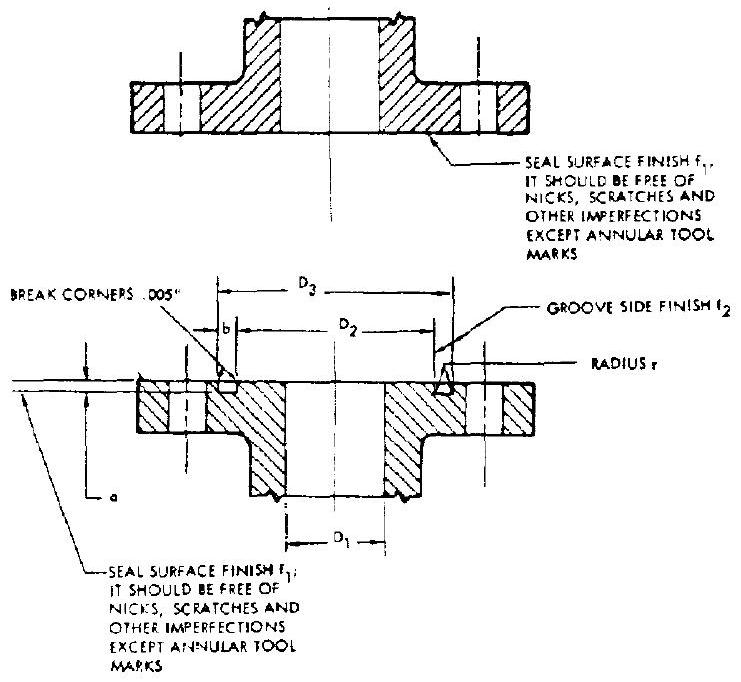 Figure 9-12.-Flange seal groove design.
sults Metal O-rings can be used in a groovetype flange, as shown in figure 9-12. Table 9-6 presents typical design data for metal O-ring flange joints.
Spiral-Wound Gaskets for Flange Joints
Spiral-wound gaskets manufactured by the Flexitallic Gasket Co . have been used extensively in rocket engine flange joints for liquid oxygen and hot gas (up to ) services. Pressures are generally kept below 1000 psi . The gaskets (detail shown in fig. 9-13) are made of spiral-wound 304 stainless-steel ribbon, with a Canadian asbestos filler. It is not recommended that gasket widths of less than inch
TABLE 9-5.-Typical Elastomer O-Ring Flange Joint Design Data [All dimensions in inches]
| Nominal O-ring cross section | Actual O-ring cross section | Minimum squeeze | Depth of groove. a | Width of groove. b | Bottom radius. | Seal surface finish. | Seal surface finish, |
|---|---|---|---|---|---|---|---|
| 1/16 | 0.017 | 3/32 | 1/64 | 64 rms | 64 rms | ||
| 3/32 | . 020 | 9/64 | 1/64 | ||||
| 1/8 | . 025 | 3/16 | 1/32 | ||||
| 3/16 | 030 | 9/32 | 1/32 | ||||
| 1/4 | . 039 | 3/8 | 1/16 |
TABLE 9-6.-Typical Metal O-Ring Flange Joint Design Data [All dimensions in inches]
| Nominal O-ring, OD | Actual O-ring size | Flange groove dimensions | |||||
|---|---|---|---|---|---|---|---|
| Tube OD +0.005 -0 | Tube OD +0.003 - 0 | Wall thickness | maximum | -0 | - 0 | ||
| 1 | 1.000 | 0.061 | 0.009 | 0.867 | 1.005 | 0.042 | |
| 1-1/2 | 1.500 | . 061 | 009 | 1.367 | 1.505 | 042 | |
| 2. | 2.000 | . 061 | . 009 | 1.867 | 2.005 | 0.042 | |
| 2-1/2 | 2.500 | . 061 | 011 | 2.367 | 2.505 | 042 | |
| 3 | 3.000 | . 061 | 011 | 2.867 | 3.005 | . 042 | |
| 4. | 4.000 | 094 | 011 | 3.801 | 4.005 | . 075 | |
| 5 | 5.000 | . 094 | . 011 | 4.801 | 5.005 | . 075 | 32 rms |
| 6 | 5.000 | . 094 | . 011 | 5.801 | 6.005 | . 075 | |
| 8 | 8.000 | 124 | . 011 | 7.741 | 8.005 | 105 | |
| 10 | 10.000 | 124 | . 011 | 9.741 | 10.005 | 105 | |
| 15 | 15.000 | 124 | . 011 | 14.741 | 15.005 | 105 | |
| 20. | 20.000 | 124 | . 011 | 19.741 | 20.005 | 105 | |
| 30 | 30.000 | 124 | . 011 | 29.741 | 30.005 | 105 |
See fig. 9-12 for flange design. Duct diameter may be equal to . be used. These gaskets are made to various stiffnesses (spring rates) by varying the tension of the wrapping. The harder gaskets are recommended for the higher pressures.
The gaskets are used in groove-type flanges, as shown in figure 9-12. For optimum results, tool marks on sealing surfaces should be con- centric. Typical design data for spiral-wound gasket flange joints are presented in table 9-7. Gaskets of this type require high compressive loads. The values range from 6000 to 25000 psi . The amount of gasket compression is controlled by metal-to-metal contact of the flanges, with allowance for maximum tolerance buildup of
Table 9-7.-Typical Spiral-Wound Gasket Flange Joint Design Data [All dimensions in inches]
| Gasket dimensions | Approximate required compressive load, lb at deflection | Flange groove dimensions | |||||||
|---|---|---|---|---|---|---|---|---|---|
| A diameter | B diameter | Sealing area, sq. in. | 0.025 | 0.035 | а | r | |||
| 1.000 | 1.375 | 0.442 | 8200 | 10600 | 0.900 | 1.425 | for fluid pressure below 200 psi ressure above 200 psi Isd әлоqe | ||
| 1.500 | 1.875 | . 638 | 8300 | 11500 | 1.400 | 1.925 | |||
| 2.000 | 2.375 | . 835 | 9000 | 12700 | 1.900 | 2.425 | |||
| 2.500 | 2.875 | 1.031 | 9800 | 14100 | 2.400 | 2.925 | |||
| 3.000 | 3.375 | 1.227 | 10800 | 15600 | 2.900 | 3.425 | |||
| 4.000 | 4.375 | 1.620 | 12950 | 18600 | 3.900 | 4.425 | |||
| 5.000 | 5.500 | 3.056 | 23000 | 32400 | 4.875 | 5.560 | 0.010 | 125 mms | |
| 6.000 | 6.500 | 3.645 | 26400 | 37000 | 5.875 | 6.560 | |||
| 8.000 | 8.500 | 4.832 | 33600 | 43000 | 7.875 | 8.560 | |||
| 11.000 | 11.750 | 11.110 | 73600 | 97000 | 10.875 | 11.810 | |||
| 15.000 | 15.750 | 15.040 | 98600 | 122500 | 14.860 | 15.820 | |||
| 20.125 | 21.000 | 24.150 | 153000 | 178500 | 19.965 | 21.080 | |||
| 25.000 | 25.875 | 29.900 | 186500 | 206000 | 24.840 | 25.955 |
[^10]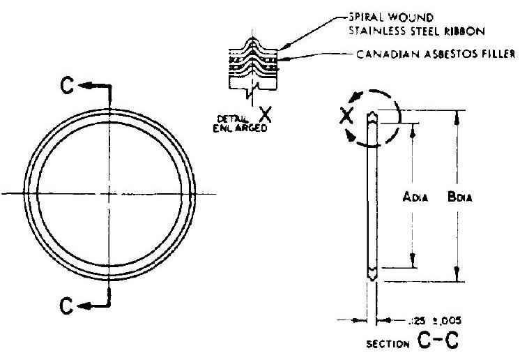 Figure 9-13.-Spiral-wound gasket for flange joints.
gasket thickness and groove depth. One difficulty with spiral-wound gaskets is the presence of erratic compression loads, due to thickness tolerances and variations in wrapping. Another is their tendency to indent the flange sealing surfaces, particularly when the flanges are of aluminum.
Pressure-Actuated Seals for Flange Joints
An ingenious approach toward attaining better seal deflection capabilities to accommodate deformations of the flange joint under working loads is the pressure-actuated type seal, shown in figure . The spring effect is achieved by a metal, circular seal having a U-shaped cross section. When such a seal is compressed between the surfaces of a flange joint, the high points at its open ends make contact with the flange surfaces. If properly designed, the springlike legs flex to follow flange deflections.
The open end of the seal must always be oriented toward the inside of the flange joint. Thus the internal fluid pressure is utilized to generate a considerable portion of the seal contact load. Pressure-actuated seals are installed in a concentric groove cut into the flange joint. This limits the amount of total flange preload transmitted through the contact points of the seal. The following correlations are established for the seal design shown in figure 9-14 for the approximation of seal contact loads:
 OPEN CROOVE
INSTALLATION
OPEN CROOVE
INSTALLATION
 CLOSED GROOVE
installation:
CLOSED GROOVE
installation:
where
| seal contact load per inch of seal circumference without internal fluid pressure, |
|---|
| seal contact load per inch of seal circumference with internal fluid pressure, lb/in |
| modulus of elasticity of the seal material, psi |
| end thickness of the seal leg, in |
| length of the seal leg, in |
| d = seal deflection in the flange joint, in (i.e., the difference between initial seal width and flange groove depth) |
| internal fluid pressure, psi |
MATERIAL - 4340 STEEL HEAT TREATED TO 160.000 - 180.000 PSI
FTNISH T}\mathrm{ ELECTROEESS NICKEL. PLATE 0010 - .0012 INCH EMBRITTLEMENT RELIEVED.
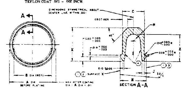 (1) THESE SURFACES TU BE FREE OF NICKS EURRS AND TOOL MARKS EXCEPT ANVULAR TOOL
MARKS MARKS
(3) FLAT WTTHIN OOOB INCH PER INCH CIRCUWFERENCE.
(3) Parallel to surface utthis rats inch per inch circumference
(4) THICKNESS OF TEFLON COATING ON THESE SURFACES OPTIOSAL.
(1) THESE SURFACES TU BE FREE OF NICKS EURRS AND TOOL MARKS EXCEPT ANVULAR TOOL
MARKS MARKS
(3) FLAT WTTHIN OOOB INCH PER INCH CIRCUWFERENCE.
(3) Parallel to surface utthis rats inch per inch circumference
(4) THICKNESS OF TEFLON COATING ON THESE SURFACES OPTIOSAL.
Figure 9-14.-Rocketdyne Naflex pressureactuated seal design for flange joints. design factor. This is a function of seal leg configuration, its value ranging from 0.04 to 0.8
Generally, the contact surfaces of pressureactuated seals are coated with a material of a lower elastic modulus than that of the material from which the seal is made. Thus the seal material can be utilized to achieve the springlike properties required for maximum deflection capability, while the coating material provides the properties needed to establish the intimate contact required to prevent leakage between seal and flange surfaces. To prevent leakage, sufficient compressive stress must be developed in the coating to make it flow into imperfections on the flange surfaces. The required coating compressive stress may be determined by
where seal coating compressive stress, psi modulus of elasticity of the coating material, psi depth of the imperfections on the flange sealing surfaces, in thickness of the coating, in Many versions of pressure-actuated seals have been applied to rocket engines. Rocketdyne has developed the Naflex-type pressure-actuated seals, made of alloy steel and coated with a thin layer of Teflon. They are most effective for cryogenic ( ) and high-pressure (up to services. Figure 4-32 illustrates a typical Naflex seal installation at the flange joint between thrust chamber and liquid oxygen dome. Design details and data for typical Naflex flange joints may be seen in figure 9-14. Also see table 9-8. For hot gas applications, up to approximately , the seals may be coated with soft metals such as copper, aluminum, or gold.
For certain stringent applications, all propellant and turbine gas flanges in a rocket engine can be equipped with a Naflex-type dual static seal incorporating an intermediate cavity between high-pressure and low-pressure sealing areas. A seal drain line may be connected to the intermediate cavity, as shown in figure 9-15. This line can also be used to measure the seal leakage rate, if any. This arrangement may also be applied to pneumatic system flange joints, to monitor leakage.
Table 9-8.-Typical Design Data of Naflex Pressure-Actuated Seals and Flange Joints [All dimensions in inches]
| Seal dimensions | Flange groove dimensions | |||||||||||
|---|---|---|---|---|---|---|---|---|---|---|---|---|
| A diameter | B diameter | H | a | |||||||||
| +0 | (REF) | +0 | +0 | +0.004 | + 0 | +0.005 | + 0 | +0.010 | +0.002 | r | ||
| -0.005 | -0.005 | -0.005 | -0.003 | - 0 | -0.003 | -0 | -0.010 | - 0 | - 0 | |||
| 0.934 | 0.464 | 0.235 | 0.155 | 0.190 | 0.433 | 0.948 |  0.148 173 | 32 rms | ||||
| 1.496 | 1.026 | 235 | . 155 | 190 | 995 | 1.510 | ||||||
| 2.058 | 1.548 | 1.507 | 2.072 | |||||||||
| 2.621 | 2.111 | 0.018 | 0.139 | 2.070 | 2.635 | |||||||
| 3.080 | 2.570 | 255 | 160 | . 210 | 2.529 | 3.094 | ||||||
| 3.620 | 3.110 | 3.070 | 3.635 | |||||||||
| 4.618 | 4.108 | 0.037 | - | 4.070 | 4.635 | |||||||
| 5.616 | 5.116 | 1. | 1 | 5.070 | 5.635 | |||||||
| 6.614 | 6.114 | 1 | 6.070 | 6.635 | ||||||||
| 8.610 | 8.110 | . 250 | . 017 | . 182 | . 164 . 164 | . 205 | 8.070 | 8.635 | ||||
| 10.606 | 10.106 | 10.070 | 10.635 | |||||||||
| 15.596 | 15.096 | 15.070 | 15.635 | |||||||||
| 20.870 | 20.370 | 20.320 | 20.885 |
[^11]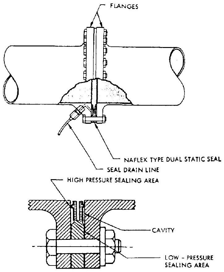 Figure 9-15.-Typical design of a flange joint with Naflex-type dual static seal and seal drain line.
Sample Calculation (9-3)
The following data are given for a Naflex seal represented by section A-A of figure 9-14: Design factor, . The seal material modulus of elasticity, . The flange seal groove depth, . The thickness of the Teflon coating, , with a modulus of elasticity, . Estimate the seal coating compressive stresses with and without an internal pressure, p, of 2000 psi . Also, determine the allowable depth of imperfections on the flange sealing surfaces.
Solution
The seal deflection
From equation (9-19), the seal contact load without internal pressure
From figure , the seal land of contact . Thus, the seal coating compressive stress without internal pressure
From equation (9-20), the seal contact load with internal pressure
The seal coating compressive stress with an internal pressure of 2000 psi
The allowable depth of imperfections on the flange sealing surfaces should be calculated from the initial coating compressive stress, using equation (9-21):